


SERVICE SUPPORT
SERVICE SUPPORT
CONTACT USCONTACT US
Headquarters address: No. 333 East Feiyue Road, High-tech Zone, Changchun, Jilin, China
National Unified Sales Hotline: 0431-84627295
Company email:sale@cddtech.com
Installation instructionsABOUT US
Installation instructions
The installation
1. Matters needing attention
1.1. Try to choose the machining surface as the installation surface.
1.2 When the installation surface is a non-processed plane, a flat mat shall be installed at the back of the ruler to ensure the stability and reliability of the grating ruler installation.
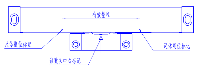
1.3 The maximum stroke of the machine tool or equipment shall be less than or equal to the effective range of the grating ruler (the two dots on the ruler are the maximum stroke at both ends). If the maximum stroke of the machine tool or equipment is greater than the effective range of the grating ruler. The limit switch should be installed in the corresponding position or the grating ruler with longer range should be replaced by our company. As shown in the figure:
1.4 The reading head with signal line should be fixed on the non-moving parts to facilitate the signal line wiring and simplify the overall layout of the machine or equipment.
1.5 After the cover of the frame is rotated 180°, the direction of the wire can be changed. When the cover of the frame is reinstalled, do not press the wire inside the frame.
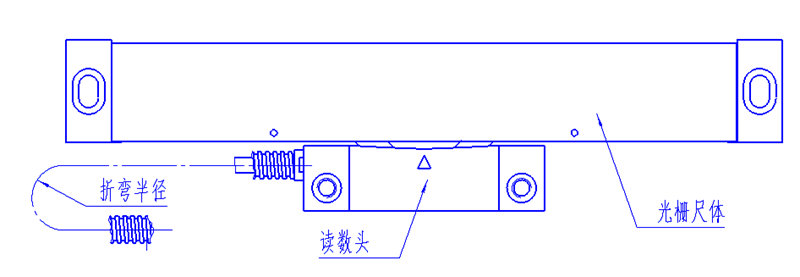
1.6 During installation, the signal line bending radius shall be greater than 50mm. As shown in the figure:
1.7 The opening direction of the grating ruler sealing strip should avoid the direct sputtering or impact of processing chips, oil, water, coolant, dust and other sundry objects. As shown in Figure D:

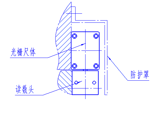
1.8 If the installation space allows, it is recommended to order our company's installation accessories, which can protect the products from dust, oil and impact. As shown in the figure:
1.9 If you design, process and install the attachment, please follow the principle of short and less to ensure the strength of attachment connection or combination connection.
2. Installation standards
2.1 Basic surface standards
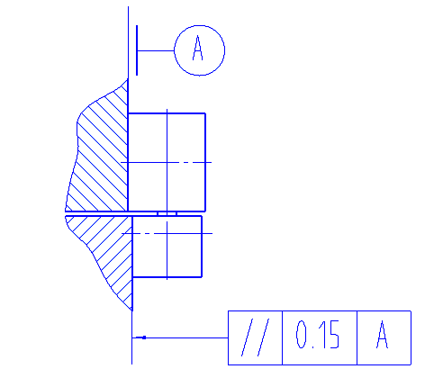
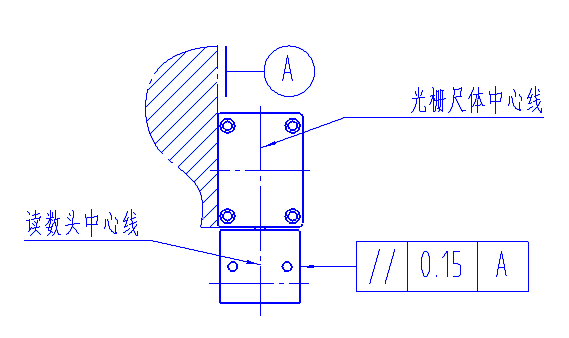
2.1.1 If the base surface of ruler body is parallel to the base surface of reading head, the parallelism shall be ≤0.15mm. As shown in the figure:
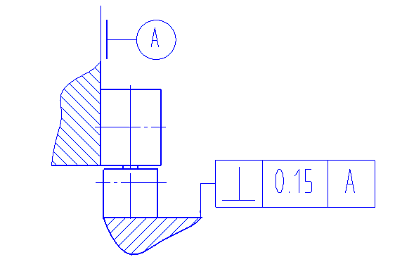
2.1.2 If the base surface of ruler body is perpendicular to the base surface of reading head, the perpendicularity shall be ≤0.15mm. As shown in the figure:
2.2 Ruler body standard
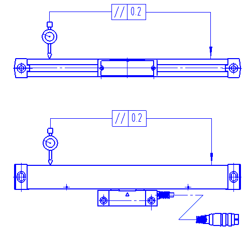
The two vertical surfaces of the ruler are parallel to the two moving directions of the machine tool or equipment
The degree shall be ≤0.20mm, as shown in the figure:
2.3 Reading head standard
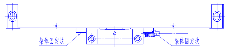
2.3.1 During packaging and transportation, there are plastic fixed blocks on both sides of the reading head, which must be removed before installation and debugging. As shown in the figure:
2.3.2 The adjacent clearance between the reading head and the ruler shell is 1.2 ~ 1.5mm, as shown in the figure:
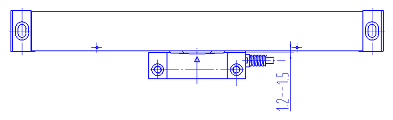
2.3.2 The adjacent clearance between The reading head and The ruler shell is 1.2 ~ 1.5mm, as shown in The figure:
3. Check the power supply
3.1 Move the grating ruler and check whether the grating ruler measurement system is within the effective range and the counting is normal.
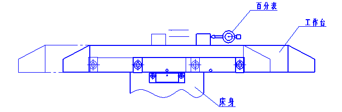
3.2. When the dial indicator returns to zero, check the measuring system of grating ruler. The error to zero should be no more than ±0.010mm. As shown in the figure:
Changchun Yuheng Optical Co. LTD
Changchun Optical digital display Technology Co. LTD
